


Safety and Installation Instructions
Collection:This document applies to all RUGGEDSOLAR® RUGGEDFLEX™ modules listed in Table 1
Contents of this manual are subject to change without notice. For the latest updates please refer to www.ruggedsolar.net
©2020 RUGGED SOLAR PRODUCTS PRIVATE LIMITED | v1.0.2020
1.0 Introduction
This manual provides safety and installation instructions for RUGGEDSOLAR® (“Manufacturer”) RUGGEDFLEX™ photovoltaic (PV) modules.
IMPORTANT! Please read this manual in its entirety before installing, wiring, or using this product in any way. Failure to comply with these instructions will invalidate the Manufacturer’s Limited Warranty for PV Modules.
1.1 Disclaimer of LiabilityThe installation techniques, handling, and use of this product are beyond company control. Therefore, RUGGED Solar assumes no responsibility for loss, damage or expense resulting from improper installation, handling, or use.
1.2 Limited Warranty The Limited Warranties do not apply to any of the following:PV Modules subjected to: (1) misuse, abuse, neglect or accident; (2) alteration or improper installation (improper installation includes, without limitation, installation or array that does not comply with all Manufacturer’s installation and wiring instructions (as may be amended and updated from time to time at Manufacturer’s sole discretion); Manufacturer’s operations and maintenance instructions of any type (as may be amended and updated from time to time at Manufacturer’s sole discretion), and all national, state, and local laws, codes, ordinances, and regulations); (3) repair or modification by someone other than a Manufacturer approved service technician; (4) conditions exceeding the voltage, wind, snow load specifications, and any other operational specification; (4) power failure surges, lightning, flood, or fire; (5) damage from persons, insects, animals, or industrial chemical exposure; (6) panel breakage from impact or other events outside Manufacturer’s control. Additional terms and conditions apply. See the RUGGEDSOLAR® Manufacturer’s Limited Warranty for full terms and conditions.
2.0 Safety Precautions
Before installing this product, read all safety instructions in this document.
*** WARNING ***
- Module interconnection cables pass direct current (dc) and are energized when the panel is exposed to light. Current may also be flowing if the panel is connected to a battery or other power source regardless of illumination.
- Direct current will arc across a gap and may cause injury or death when improper connection or disconnection is made;
- Contacts and cable with frayed or exposed conductors should not be used. Contact with exposed conductors may result in electrical shock, injury and possible death.
- DO NOT connect or disconnect modules when they are energized by exposure to light or external power sources such as a battery. Disconnection under load will result in Arcing and damage to the connector.
- DO NOT short the leads together. If inadvertent shorting occurs, Cover the panel completely with non-transparent material or turn the panel facing down, obscuring all light, before attempting to disconnect the cables.
- High voltage may be present when modules are interconnected in series. High currents may be present when modules are connected in parallel.
- All installations must be performed in compliance with any applicable local codes.
- For United States jurisdictions, installations shall be performed in compliance with the National Electrical Code (NEC) and any applicable local codes.
- For Canadian jurisdictions, installations shall be in accordance with CSA C22.1, Safety Standard for Electrical Installations, Canadian Electrical Code, Part 1 and any applicable local codes.
- There are no user‐serviceable parts within the module. Do not attempt to repair any part of the module.
- Installation should be performed only by qualified personnel.
- ONLY open packing box and remove RUGGEDFLEX™ modules at the time of installation. DO NOT keep modules uninstalled and out of original packing box.
- Do not stand on, drop, scratch, or allow objects to fall on modules as it may damage them and void the warranty.
- Do not walk on panels.
- Do not carry panels by the electrical cables.
- Do not place anything on the modules, even for a moment because resulting residue may damage or stain the surface.
- Broken or cracked J‐boxes, cables and/or connectors are electrical hazards as well as laceration hazards. Customers should remove any such module from service and contact Manufacturer for disposal instructions.
- Broken or cracked metal ribbons in the panel are electrical hazards. Customers should remove any such module from service and contact Manufacturer for disposal instructions.
- Do not install or handle the modules when they are wet or during periods of high wind or extreme weather.
- Do not allow water to pool on or near the module.
- Manufacturer recommends a conservative minimum cable bend radius equal to or greater than 40 mm (1.5”).
- Contact Manufacturer if maintenance is necessary.
- Please retain these instructions for future reference.
3.0 Electrical Characteristics
Electrical characteristics of the modules are described in Table 1 below. For all modules, the maximum series fuse rating is 15A. Under normal conditions, a photovoltaic module may experience conditions that produce more current and/or voltage than reported at Standard Test Conditions. Accordingly, the values of ISC and VOC marked on the modules should be multiplied by a factor of 1.25 when determining component voltage ratings, conductor capacities, fuse sizes and size of controls connected to the module output. Refer to Section 690‐8 of the NEC for an additional 1.25 Safety factor which may be applicable.
Table 1: Electrical Characteristics1
|
Typical Electrical Data at STC: 25° C, 1000 W/m2 and AM 1.5 |
||||||
|
Model |
RF-03512 |
RF-05012 |
RF-09812 |
RF-06024 |
RF-09024 |
RF-18024 |
|
Nominal Power (WpVp) |
35Wp18Vp |
50Wp18Vp |
98Wp18Vp |
60Wp30Vp |
90Wp30Vp |
180Wp30Vp |
|
Power Tolerance |
+/-5% |
+/-5% |
+/-5% |
+/-5% |
+/-5% |
+/-5% |
|
Rated Voltage (Vmpp) |
18.3 V |
18 V |
18 V |
30 V |
30 V |
30 V |
|
Rated Current (Impp) |
1.91 A |
2.77 A |
5.55 A |
1.94 A |
2.92 A |
5.84 A |
|
Open circuit voltage (Voc) |
20 V |
19.8 V |
19.8 V |
33.8 V |
33.8 V |
33.8 V |
|
Short circuit current (Isc) |
2.10 A |
3.04 A |
6.11 A |
2.14 A |
3.20 A |
6.42 A |
|
Dimensions(LXWXH) |
421*523.5*3 mm |
530x560*3.2 mm |
550*1062*3.7mm |
550*658.7*3.2 mm |
550*950*3.7 mm |
931*1063.5*3.7 mm |
|
Weight, Kgs |
2.5 |
3.0 |
5.0 |
3.6 |
5 |
9 |
|
Power Temp Coefficient |
–0.35%/° C |
–0.35%/° C |
–0.30%/° C |
–0.30%/° C |
–0.30%/° C |
–0.30%/° C |
|
Voltage Temp Coefficient |
–58.9 mV/° C |
–58.9 mV/° C |
–55.8 mV/° C |
–83.7 mV/° C |
–83.7 mV/° C |
–83.7 mV/° C |
|
Current Temp Coefficient |
2.6 mA/° C |
2.6 mA/° C |
3.5 mA/° C |
3.5 mA/° C |
3.5 mA/° C |
3.5 mA/° C |
|
Max. System Voltage |
RUGGEDSOLAR® RUGGEDFLEX™ modules are to be used in battery charging applications, e.g. 12V or 24V batteries. |
|||||
|
NOTE: As per various electrical codes and regulations, solar panels operating at system voltages > 50VDC must be UL certified for the US and IEC certified for other countries. RUGGEDSOLAR® RUGGEDFLEX ™ is pending UL and IEC certification. |
||||||
|
Series Fuse Rating |
15 A |
|||||
4.0 Electrical Connections
The terminals, wires and/or connectors used in these panels allows for modules to be connected in series or parallel. However, connecting the panels in this manner can put the by‐pass diode in the panel and the battery at risk for damage and could create a safety issue. Please read the WARNING! note below.
IMPORTANT – ONLY CONNECT IN SERIES OR PARALLEL THE SAME MODEL OF SOLAR MODULE. THE EXACT SPECIFICATIONS MUST MATCH ON ALL PANELS CONNECTED IN SERIES OR PARALLEL, INCLUDING WATTS, VOLTS AND CURRENT. WIRES AND CONNECTORS SHOULD ALSO BE IDENTIAL IN MAKING ALL CONNECTIONS BETWEEN MODULES IN SERIES AND/OR PARALLEL.
Series Connection:
Connecting the panels in series increases the voltage of the system, so the two panels produce double the voltage as compared to one panel. This high voltage can cause damage to the battery and could cause safety issues. Please read the WARNING! note below.To connect panels in series, connect the Negative (‐) TERMINAL of panel #1 to the Positive (+) TERMINAL of the panel #2. See Figure1 left.
Parallel Connection:
Connecting the panels in parallel increases the current of the system, so the two panels produce double the current as compared to one panel. This high current may cause damage to the battery and by‐pass diode in the junction box and cause a safety issue. Please read the WARNING! note below.To connect panels in parallel, connect the Positive (+) TERMINAL of panel #1 to the Positive (+) TERMINAL panel #2 Connect the Negative (‐) TERMINAL of panel #1 to the Negative (‐) TERMINAL of panel #2. See Figure 1 Right. In this configuration, cable adapters will be needed.
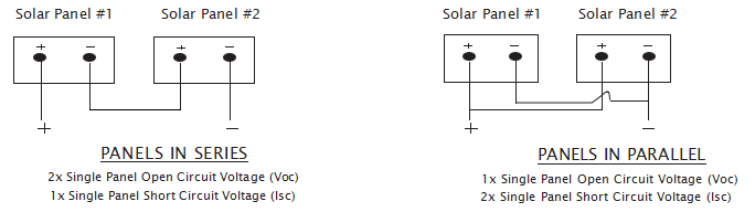
Figure 1: Schematic of two panels in series and parallel.
WARNING!
- Connecting panels in series will increase the voltage output of the panels.
- DC voltages may reach levels greater than 40 V DC, in high illumination conditions (>1000 W/m2).
- If attached to a low voltage battery, e.g. a 12 V battery, this high voltage could cause damage to the battery and could cause a safety issue. MAKE SURE TO USE THE CORRECT PV CHARGE CONTROLLER (CCU) WITH RUGGEDSOLAR® MODULES.
- The charging characteristics of any battery and the PV charge controller (CCU) should always be checked for compatibility with the current and voltage output of the panels prior to use.
For models not shown here, please contact RUGGED Solar technical support or visit www.ruggedsolar.net. Electrical parameters are measured at Standard Test Conditions (STC). The series fuse must have an interrupting rating that is equal to or greater than the maximum fault current that the fuse is required to interrupt, including contributions from all connected sources of energy.
- Manufacturer does not recommend connecting these panels in parallel without proper system and safety protection.
- Connecting panels in parallel will double the current output of the panels. DC Currents may be greater than 12 amps for 100 W or higher panel output and greater than 6amps for 50 W panels, in high illumination conditions (>1000 W/m2).
- If shading occurs without additional electronic components, such as a blocking diode, the by‐pass diodes may be damaged leading to further panel damage and unsafe conditions including fire.
- If Paralleled panels are attached to a PV charge controller (CCU) and battery for charging, the high current may cause damage to the PV charge controller (CCU) and battery and subsequent safety issues.
- The charging characteristics of any battery should always be checked for compatibility with the current and voltage output of the PV charge controller (CCU) and PV panels prior to use.
5.0 Module Mounting
The Manufacturer’s Limited Warranty for PV Modules is contingent upon modules being mounted in accordance with the requirements described in this section.
5.1 Site Considerations
RUGGEDSOLAR® RUGGEDFLEX™ modules should only be mounted in locations that meet the following requirements:
Operating Temperature: All RUGGEDSOLAR® modules must only be mounted in environments that ensure they will operate within the following temperatures:
| Operating Temperature range | ‐40° C to +85° C ‐40° F to +185° F |
Excluded Operating Environments
Certain operating environments are not recommended for RUGGEDSOLAR® RUGGEDFLEX™ modules and are excluded from the Manufacturer’s Limited Warranty. These include but are not limited to contact with liquids with pH greater than 8.5 or less than 6.5, large hail and other projectiles, fire, meteorites, lava flow and volcanic eruptions. RUGGEDSOLAR® RUGGEDFLEX™ modules can withstand high wind, mild blunt-force impact, steady vibration associated with motorized equipment, and occasional submersion in water when securely attached to a flat or slightly curved (less than 30 degrees) along a single axis, rigid and fixed rigid surface so that the module does not move, is dislodged, is bent or twisted more than 30 degrees or on more than one axis, or otherwise experiences significant mechanical stress.
5.2 Mounting Configurations
Modules may be mounted at any angle, from horizontal to vertical, but to reduce the buildup of dirt on the surface of the module, modules should be mounted at a minimum of 10 degrees, and to ensure proper operating efficiency, modules should not be installed at greater than 45 degrees other than in extreme latitudes.
Modules should be mounted using the grommet holes as attachment points and using an outdoor waterproofing adhesive on the panel backside. When using adhesive on the backside of the panel, the panel can no longer be removed without permanent damage and voiding of the Manufacturer’s Limited Warranty. If adhesive is not used on the backside of the panel for installation, and only screws are used to secure the panel through the grommet holes, then it can be removed and installed again, although doing so is not covered under the Manufacturer’s Limited Warranty and would void the Manufacturer’s Limited Warranty.
5.3 Module Handling
Use gloves when handling modules. The module is sensitive to oils and abrasive surfaces, which may lead to scratches and irregular soiling. Do not place modules such that the module encounters abrasive surfaces and minimize any contact with the module in general. Do not place anything on the modules. Never lift or move the module using the cables or the junction box under any circumstances. Remove any fingerprints by washing the module as described in Section 6.0 below.
Modules should be handled without bending or twisting of the panels prior to permanent installation on a fixed, rigid surface. The panels are designed to withstand a 30‐degree bend in the panel, top to bottom where the top is the side with the junction box and wires. Additionally, no sharp objects should be placed in contact with the panel. This can result in scratching or marring of the surface of the panel and/or damage to the solar cells or connectors in the panel, resulting in decreased power output and potentially a safety hazard, see section 2.
Junction boxes, cables and connectors should never be subjected to a sharp or blunt force. This can result in a broken or cracked junction box, cable or connectors such that the panel should not be used. See section 2.
6.0 Maintenance and Cleaning
Users should inspect all modules annually for safe electrical connections, sound mechanical connections, and freedom from corrosion.
Periodic cleaning of module has resulted in improved performance levels, especially in regions with low levels of annual precipitation; therefore, Manufacturer recommends periodic cleaning of the modules.
To clean a module, wash its surface with potable, non‐heated water and normal dishwashing soap (Do not use ammonia, bleach, alcohol-based solvents, high acidic or basic liquids.) Normal water pressure is adequate. Some fingerprints, stains, or accumulations of dirt and greasy grime on the surface may be removed with a 3% soap‐and‐water solution. Wet the module surface with the solution, let it stand for five minutes, and then wet them again and use a soft sponge or seamless cloth to wipe the surface in a circular motion. Do not use harsh industrial‐strength cleaning materials such as aggressive chemicals, scouring powder, steel wool, scrapers, blades, or other sharp instruments to clean the module - Use of such materials will void the product warranty. In extreme cases, mineral spirits applied to a clean cloth can be used to remove dirt and greasy grime.
7.0 Disposal of Modules
RUGGEDSOLAR® modules should be disposed of in accordance with all national, state, and local laws, codes, ordinances, and regulations. Manufacturer takes no responsibility in the disposal of any modules, nor does it take responsibility for informing users of their legal obligations and potential liabilities associated with the ownership and disposal of any PV modules. It is the sole responsibility of the user to be informed of all national, state, and local laws, codes, ordinances, and regulations associated with the ownership, operation, and disposal of any PV modules.